Questions? 800-523-5874 | [email protected]
- TEM Grids
- Prepmaster™ Specimen Preparation Robot
- TEM Window Grids
- Omniprobe Nanomanipulation Systems
- K-kit Wet "Liquid" TEM Kit
- Specimen Mounts
- SEM Specimen Holders
- Index and Finder SEM Grids
- SEM for Forensics
- SEM Sample Preparation Station Materials
- Cryogenic Personal Protection Equipment
- Cryo Dewars & Flasks
- Cryo-EM Grids & Grid Storage
- Cryogenic Vials & Racks
- Cryo-EM Vitrification Supplies
- Prepmaster™ Specimen Preparation Robot
- Laboratory Microwave Ovens
- LYNX II Automated Tissue Processor
- EMS Poly III
- Microtomes
- Tissue Slicers
- Heaters & Chillers
- SEM Cooling Stage
- Glow Discharge Systems
- Sputter Coaters & Carbon Coaters
- Stages
- Freeze Dryers
- Critical Point Dryers
- Cryo-SEM Preparation System
- Specimen Transfer Systems
- Decontaminators
- Desiccators
- Centrifuges
- Dry Baths
- Stirrers, Hot Plates
- Vortexers & Magnetic Mixers
- Rotators & Rockers
- Ovens & Incubators
- Vibration Isolation
- Air Sampling
- Vacuum Pumps
EMS Technical Data Sheets

Vibration Isolation Platform - VIP Series 320 User Manual
EMS Catalog #67120-12 to 67127-24
Introduction
The VIBe vibration isolation baseplate from Electron Microscopy Sciences is a compact, effective and easy-to-use platform that significantly reduces effect of disturbing environmental vibrations on sensitive instruments such as microscopes, inspection or analysis equipment. All VIBe units feature a black powder-coated steel plate and patented mechanical isolators that provide both vertical and horizontal vibration isolation, there are no air lines, compressors or other accessories needed to provide effective isolation performance.
The Vibe is available in four standard shapes, two rectangular and two triangular, that have been designed to satisfy the widest range of application needs. The two rectangular platforms come in 12"x18" and 18"x24" sizes and can be equipped with isolator bearings to support payloads from 5lbs to over 350lbs. The triangular models have been designed specifically to accommodate a large assortment of microscope footprints from all leading manufacturers.
At the heart of the VIBe are the IB isolator bearings which are available in discrete payload ranges as identified by their part number. For very light instruments, model IB-1018 isolates total payloads from 10lbs to 18lbs per bearing and for heavy instruments IB-50100 isolates total payloads from 50lbs to 100lbs per bearing. We offer different models of IB bearings that effectively cover a load range from 10lbs to 100 lbs. This allows users to configure the proper size platform and bearings in the required locations on the baseplate to support and isolate their instrument, even if the load is not uniform, as in the case of microscopes which are typically heavier in the rear by as much as 50%.
Each bearing is a self-contained unit that provides both vertical and horizontal isolation for that specified load range. The isolators feature a 6.7Hz vertical resonance frequency that begins isolating at 9Hz and a horizontal resonance of 6.2Hz with isolation beginning at 9Hz. This is sufficient performance to eliminate more than 85% of vibration noise seen within typical laboratories. The IB bearings attach to the VIBe baseplate using specially designed brackets that feature a threaded aperture to allow leveling adjustment of the VIBe baseplate.
Getting Started
Please read this instruction manual thoroughly before assembling the isolation system. The individual components have been assembled at the factory and require only final system assembly and performance adjustment.
Unpacking and Inspection
The components of your VIBe are packed in individual, labeled boxes. Carefully inspect all components for shipping damage. Report any shipping damage immediately.
Safety Considerations
The following terms are used in this manual that relate to your safety.
 |
WARNING
|
| Warning is used to indicate dangers that could result in personal injury. |
|
CAUTION
|
| Caution is used to indicate situations that may result in damage to components of your Vibration Control System. |
System Placement
To ensure optimal performance from your VIBe, it should be located on a level surface. Uneven mounting surfaces may cause difficulty if their irregularity is outside of the adjustment range of the IB isolator.
Unpacking and Inspecting
Carefully unpack and remove the VIBe baseplate, brackets and isolators from their boxes. Inspect all of the parts for shipping damage. You will find a black powder coated VIB base plate, mounting brackets with two bolts per bracket and IB isolators with a rubber O-ring (see Figure 1).
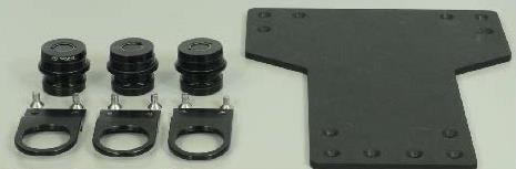
Figure 1: Vibe components. The shape of the baseplate and the number of isolators may differ depending on your system configuration.
Assembling the ViBe System
- Place the O-ring around the top of the VIB and secure it around the bearing just below the threaded portion of the IB isolator (see Figure 2).
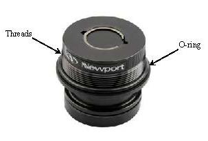
Figure 2: IB isolator assembly
- Bolt the mounting brackets to the base plate (see Figure 3).
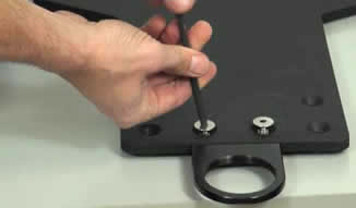
Figure 3: Mounting the VIB-BRKT to the base plate
- Next, screw the IB bearings into the brackets completely and place the VIBe in the desired location (see Figure 4).
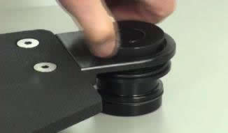
Figure 4: Installing the IB isolator into the VIB-BRKT
- Finally, place your instrument onto the base plate and adjust the IB bearing at the lowest corner if necessary to level the platform (see Figure 5).
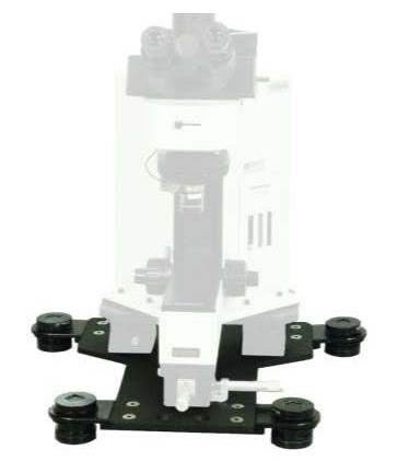
Figure 5: Instrument placed centered on the VIBe system
Check the VIBs for proper alignment
|
WARNING
|
| Do not slide platform, or move platform once a load has been placed and the bearings are compressed. Damage may occur to the bearings. |
The bottom portion of the bearing must be vertically aligned with the top portion. (The VIP can be displaced from side to side. When you push the VIP to the side with your hand, the top portion of each VIB will move relative to the bottom portion. When you remove the lateral force, the VIBs will re-center.) You may visually inspect the VIBs to see if the alignment is correct. Simply look at the sides of the VIBs and feel with your fingers to determine if they are aligned. If the alignment is not correct, move the bottom portion of the VIBs with your fingers to correct the alignment (see Figure 6).
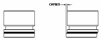
Figure 6: IB isolator alignment diagram
Leveling the Platform
Various microscope configurations place more weight on one side or end of the platform than another, compressing one bearing more than another and thus causing the platform to sit un-level. In this case, determine which bearing is deflected more than the others and turn the top half of the bearing clockwise relative to the threads in the clip that is bolted to the plate. It may be necessary to lift upwards on the platform (though not lifting the VIB off the table) to reduce the pressure on the threads and make it easier to turn the threaded cap. This action will raise the plate relative to the tabletop and level the platform (see Figure 7).
Figure 7: IB isolator height adjustment
Preloading the Isolators
The IB bearings are shipped with a special gap tool that is used to verify that the isolators are properly loaded. This gap tool measures 0.56” wide by 0.1” thick and is used to determine that the gap in the isolator is more than 0.1” but less than 0.56” (see Figure 8).
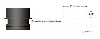
Figure 8: Gap tool dimension and measurement location
If the gap tool width fits into the gap as shown the isolator does not have sufficient loading and will not isolate properly (see Figure 9).
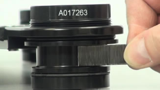
Figure 9: Gap tool width measurement showing under loaded condition
If the tool thickness does not fit into the gap the isolator is overloaded (see Figure 10).
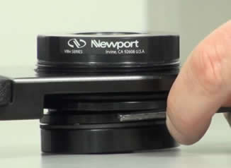
Figure 10: Gap tool thickness measurement showing overloaded condition
In either case a different load range IB bearing is needed in that location. Please be sure to verify that the appropriate load range isolators are installed in the proper location on the VIBe base plate. In some applications this may be as easy as switching isolator locations or adjusting the instrument on the platform (see Figure 11).
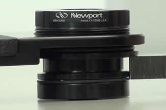
Figure 11: Gap tool thickness measurement showing correct preload
Maintenance
VIBe systems require little maintenance. No periodic maintenance is required.
Cleaning
Isolators are painted, powder coated, or zinc plated steel. This coated material is relatively corrosion resistant. It may be cleaned by applying non-abrasive liquid household cleaner to a rag and wiping the isolator. Avoid abrasive cleaners.
Online Ordering
Vibration Isolation Platforms are available online from the EMS Catalog. For ordering or product information, click here.