Questions? 800-523-5874 | [email protected]
- TEM Grids
- Prepmaster™ Specimen Preparation Robot
- TEM Window Grids
- Omniprobe Nanomanipulation Systems
- K-kit Wet "Liquid" TEM Kit
- Specimen Mounts
- SEM Specimen Holders
- Index and Finder SEM Grids
- SEM for Forensics
- SEM Sample Preparation Station Materials
- Cryogenic Personal Protection Equipment
- Cryo Dewars & Flasks
- Cryo-EM Grids & Grid Storage
- Cryogenic Vials & Racks
- Cryo-EM Vitrification Supplies
- Prepmaster™ Specimen Preparation Robot
- Laboratory Microwave Ovens
- LYNX II Automated Tissue Processor
- EMS Poly III
- Microtomes
- Tissue Slicers
- Heaters & Chillers
- SEM Cooling Stage
- Glow Discharge Systems
- Sputter Coaters & Carbon Coaters
- Stages
- Freeze Dryers
- Critical Point Dryers
- Cryo-SEM Preparation System
- Specimen Transfer Systems
- Decontaminators
- Desiccators
- Centrifuges
- Dry Baths
- Stirrers, Hot Plates
- Vortexers & Magnetic Mixers
- Rotators & Rockers
- Ovens & Incubators
- Vibration Isolation
- Air Sampling
- Vacuum Pumps
EMS Technical Data Sheets

LatticeAx™ Technical Note
EMS Catalog #7641
Using the LatticeAx™ to Cleave Structures Printed at 45 Degrees

Figure 1: Pattern rotated relative to the wafer notch or flat
This technical note explains how to use the LatticeAx™ to accurately target and cleave structures printed on <100> silicon1 and rotated 45 degrees relative to the notch or flat.
The methodology used to cleave a sample with lithography printed at an angle is identical to that described in the LatticeAx™ manual, LatticeAx™ Operation Instructions V08052013.
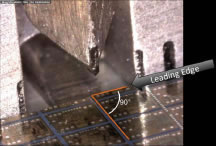
Figure 2: Features printed at 90 degrees to the leading edge of the sample
This paper provides additional details on how to cleave a specific site on the sample without the luxury of features that are aligned perpendicular to the sample's leading edge (see Figure 2.)
Preparing Your Sample for Cleaving
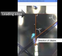
Figure 3: Layout printed at a 45 degree angle to leading edge
For the best targeting accuracy, the sample must have a clean leading edge. If the leading edge is not straight or is too rough, the target will be missed unless it is very close to the indent.
Cleaving the Sample
Target the area of interest
| A. Target | B. Indent | C. Cleave |
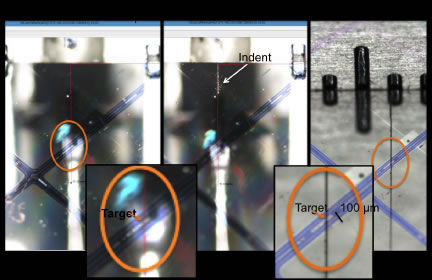
Figure 4: Target-Indent-Cleave Sequence
For all <100> silicon, the direction of the cleave will always be 90 degrees to the leading edge shown in Figure 3. This property allows the direction of the cleave and location to be defined by drawing a line perpendicular to the leading edge (see Figure 3).
Figure 4A shows the targeted feature (≈25-µm) circled in orange with the red line defining the direction of the cleave.
Position the diamond indenter over the sample and align it to the red line by using the indenter positioning knob. Turn the indenter knob just enough to make a shallow indent on the sample surface. The resulting indent will be perpendicular to the leading edge of the sample and over the drawn line (Figure 4B). Perform a cleave on a test sample to verify that the indent is perpendicular to the leading edge. If the indent appears to be at an angle, this indicates that the leading edge should be improved.
Cleave
Cleave the sample using the instructions in the LatticeAx™ manual. This results in a cleave through the target as shown in Figure 4C.
Note: It is not possible to cleave perpendicular to the pattern using this method.
1Wafers are grown from crystal having a regular crystal structure. When cut into wafers, the surface is aligned in one of several relative directions known as crystal orientations. Orientation is defined by the Miller index, like <100>.
Product Information
The LatticeAx™