Questions? 800-523-5874 | [email protected]
- TEM Grids
- Prepmaster™ Specimen Preparation Robot
- TEM Window Grids
- Omniprobe Nanomanipulation Systems
- K-kit Wet "Liquid" TEM Kit
- Specimen Mounts
- SEM Specimen Holders
- Index and Finder SEM Grids
- SEM for Forensics
- SEM Sample Preparation Station Materials
- Cryogenic Personal Protection Equipment
- Cryo Dewars & Flasks
- Cryo-EM Grids & Grid Storage
- Cryogenic Vials & Racks
- Cryo-EM Vitrification Supplies
- Prepmaster™ Specimen Preparation Robot
- Laboratory Microwave Ovens
- LYNX II Automated Tissue Processor
- EMS Poly III
- Microtomes
- Tissue Slicers
- Heaters & Chillers
- SEM Cooling Stage
- Glow Discharge Systems
- Sputter Coaters & Carbon Coaters
- Stages
- Freeze Dryers
- Critical Point Dryers
- Cryo-SEM Preparation System
- Specimen Transfer Systems
- Decontaminators
- Desiccators
- Centrifuges
- Dry Baths
- Stirrers, Hot Plates
- Vortexers & Magnetic Mixers
- Rotators & Rockers
- Ovens & Incubators
- Vibration Isolation
- Air Sampling
- Vacuum Pumps
EMS Technical Data Sheets

Application Note: Lift-Out Grid Sample Preparation
EMS Catalog #76043-01, 76043-02
Electrical contact attachment to focused ion beam (FIB) prepared lamella is a challenge. The Lift-Out Grid is designed to simplify this connection. This application note shows how a typical sample, here a piece of silicon, prepared with conventional FIB sample preparation techniques, can be attached both mechanically and electrically to a Lift-Out Grid. Further information about the development and uses of Lift-Out Grids is discussed in reference [1]. The scanning electron microscope (SEM) used for imaging, ion beam milling, and ion beam deposition in this application note was a Nova 600 Nanolab DualBeamTM-SEM/FIB. We manipulated the lamella using a Kleindiek Nanotechnik micromanipulator.
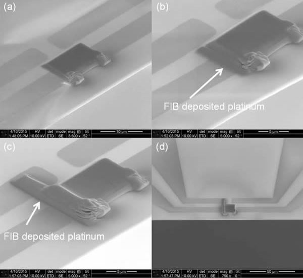
Step 1
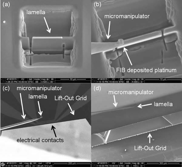
Load the Lift-Out Grid into the SEM/FIB so the grid edge faces the electron beam (the "edge-on" position). The sample should be loaded at the same time; prepare the sample lamella with a standard u-cut. A prepared lamella is shown in image (a). Next attach the micromanipulator tip to the top corner of the lamella, as shown in image (b) using a small amount of platinum deposition [2]. Cut away the bridge connecting the lamella to the support. Use the micromanipulator to move the lamella away from the support. Move the lamella near the point of convergence of the four electrical contacts, as shown in image (c). The lamella attached to the micromanipulator tip is shown from two different angles in images (c) and (d). Image (c) shows an image of the lamella detached from Lift-Out Grid surface, image (d) shows the same separation from a different angle. The different contrast in images (c) and (d) comes from the different sources used to generate the images: image (c) was made using a gallium ion source, image (d) with an electron source. The type of source used in each image acquisition is identified with an icon in the lower left corner of the image.
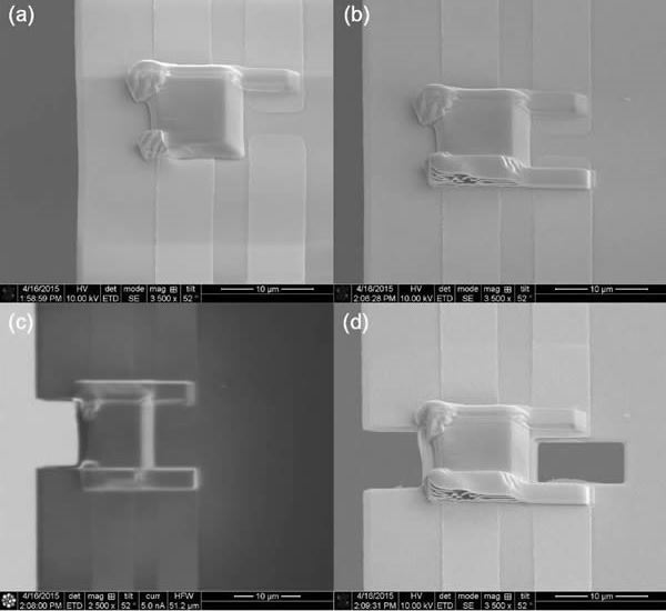
Step 2
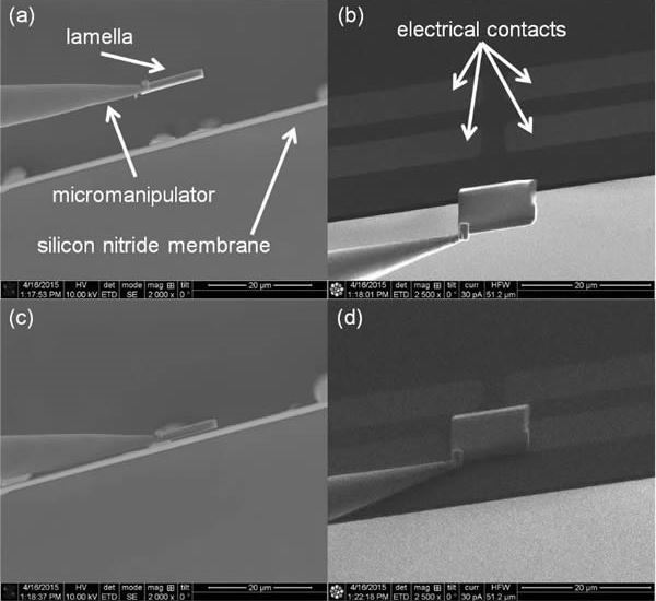
Carefully bring the lamella close to the suspended silicon nitride membrane. Switching back and forth between the SEM imaging mode, shown in (a), and the FIB imaging mode, shown in (b), can help give perspective. With careful movements the lamella can be brought into contact with the silicon nitride membrane and electrical contacts. When the lamella touches down on the membrane it will become immobile. If it needs to be repositioned it should be elevated, moved, then brought back down again. Contact is shown in images (c) and (d), and each image has a different perspective. Be careful not to switch back and forth between the electron and ion beam too often while the lamella is in contact with the insulating silicon nitride membrane. The membrane charging with difference signs can cause the lamella to be displaced.
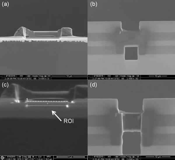
Step 3
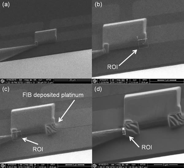
Once the lamella is in contact with the membrane, as shown in image (a), quickly attach a small amount of FIB deposited platinum to the corner opposite the micromanipulator connection. Image (b) shows the region-of-interest (ROI) on the right corner of the lamella chosen for platinum deposition. Image (c) shows the resulting deposition and a new ROI on the left corner. After both corners are "tacked down" with FIB deposited platinum, cut away the micromanipulator. The region to be cut is shown with an ROI in image (d). After the micromanipulator has been cut away, the chamber can be vented and the Lift-Out Grid repositioned for more substantial platinum deposition.
Step 4
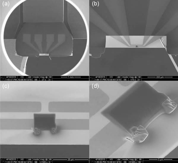
Reposition the Lift-Out Grid such that the electron beam is normal to the silicon nitride membrane. A view through the electron column down onto the Lift-Out Grid is shown in image (a). In this position the Lift-Out Grid is perpendicular to its edge-on position relative to the electron beam column used to attach the lamella. A higher magnification image of the lamella and silicon nitride membrane is shown in image (b), and an even higher magnification is shown in image (c). Image (d) shows an angled perspective of the Lift-Out Grid and lamella.
Step 5
With the lamella tacked down and the Lift-Out Grid repositioned, the next step is to attach the lamella to the metal contacts. Image (a) shows a perspective view of the lamella before any FIB deposited platinum has been used to attach the lamella to the contacts. Images (b) and (c) show a two stage process to make the electrical connection. First, to make a more gradual height change, a small amount of FIB deposited platinum is placed at the edge of the lamella, as is shown in image (b). Image (c) shows the addition of a layer of FIB deposited platinum between the front and back electrical contacts. Image (d) shows a top down perspective of the left most electrical contacts being attached to the lamella.
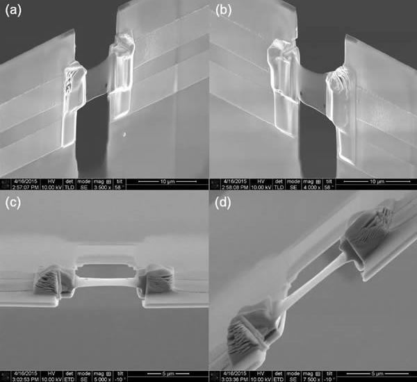
Step 6
Once the FIB deposited platinum connecting the contacts is in place on one side, it can be placed on the other, using the same procedure. Image (a) shows the lamella before the opposing FIB deposited platinum has been added, and image (b) shows the lamella after the deposition. With both platinum straps in place, the silicon nitride membrane can be cut away to provide a cleaner viewing area and to prevent electrical shorting through re-deposited platinum on the membrane's surface. Image (c) shows a top down view after the front section of the silicon nitride membrane has been cut away. The region behind the lamella is shown cut away in image (d). It is easiest to remove this nitride membrane now, rather than later.
Step 7
After the nitride membrane in front and behind the lamella has been removed, the lamella is ready to be thinned. (The Lift-Out Grid has been repositioned so that the lamella is edge-on to the electron beam.) The lamella should be positioned such that it can reach an edge-on view in the electron beam and the ion beam pathways. The edge-on view in the electron beam is shown in image (a). Image (b) shows the underside of the silicon nitride membrane before its removal. The underside should be removed first. Image (c) shows an ROI for the region to be removed by the ion beam. Post removal of the silicon nitride underside is shown in image (d).
Step 8
Once the underside of the membrane has been removed, the top and bottom of the lamella can be thinned using standard lamella thinning techniques. Images (a) and (b) show the final thinned lamella, with a thickness of ~100-200 nm. Images (c) and (d) show different perspectives of the Lift-Out Grid and attached lamella. This particular device is suitable for three different experiments. One is an in situ resistivity measurement using the four electrical contacts. Another is a gradient heating experiment: one side is heated, the other left as a cold-sink and vice versa. Finally, the electrical contacts provide a means of reading out an electron beam induced current signal from the device.
References
[1] Center for Electron Microscopy and Microanalysis, University of Southern California, Los Angeles, CA 90089, USA. Microsc. Microanal. 19 (Suppl 2), 2013. Matthew Mecklenburg et al.
[2] Nanoelectronics Research Facility, University of California, Los Angeles, California 90095, USA. From (methylcyclopentadienyl) trimethyl platinum gas, a common organometallic compound used in FIB deposition of platinum. Noah Bodzin.
[3] SiMPore Inc./TEMWindows.com, 150 Lucius Gordon Drive Suite 212, West Henrietta, NY 14586 USA. Jon-Paul DesOrmeaux and James Roussie.